Forum Replies Created
-
AuthorPosts
-
July 10, 2015 at 10:58 am in reply to: Different Types Of Broken Lines That Can Be Used In A US Design Patent #1173
david
KeymasterYes, there is more than one type of line that can be used as described on the following page:
http://www.uspto.gov/web/offices/pac/mpep/s1503.html#d0e151275Excerpts from this page from the MPEP:
“The two most common uses of broken lines are to disclose the environment related to the claimed design and to define the bounds of the claim. Structure that is not part of the claimed design, but is considered necessary to show the environment in which the design is associated, may be represented in the drawing by broken lines. This includes any portion of an article in which the design is embodied or applied to that is not considered part of the claimed design.”So, in other words, the most common type of broken line indicates the environment the device is typically used in or a structural portion of the device that is not claimed. For example, a saddle could be shown in solid lines and a horse that the saddle is on shown in broken lines. Or, if you just wanted to claim the horn on the saddle, it would be shown in solid lines and the rest of the saddle and horse in broken lines.
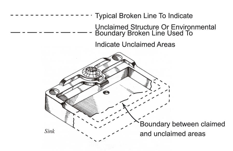
The second type of broken line can be used to indicate a boundary. A boundary line is used when the device does not have an edge line that can be converted to a broken line. For example, if it was desired to just claim the working end of a sink, it is needed to show where the claimed portion ends and this is when a boundary line is used. See Example below.
The USPTO does not specify the type of broken line that should be used, the user is free to pick the type but the description in the patent should make it clear what each line is representing. The below excerpt is from the MPEP:
” As it is possible that broken lines with different purposes may be included in a single application, the description must make a visual distinction between the two purposes; such as –The broken lines immediately adjacent the shaded areas represent the bounds of the claimed design while all other broken lines are directed to environment and are for illustrative purposes only; the broken lines form no part of the claimed design.–”
As a practical matter, other types of broken lines can be used in design patents and the description should make it clear what their purpose is. For example, a design patent drawing of a shoe might show stitching by the use of a broken line. This stitching is claimed matter as it is part of the shoe design. If this is not mentioned in the description, a patent examiner can easily misunderstand the use of the broken line whose intention was to indicate stitching as unclaimed matter.
-
This reply was modified 11 years ago by
david.
June 5, 2015 at 5:20 pm in reply to: Does Office Action Apply To Only One Figure Or Similar Ones? #1059KeymasterA: You only need to correct the figures that are mentioned in the office action. So, specifically for this case, you only need to correct FIG. 2. We see this quite frequently where a specific figure or figures is mentioned and the one beside it has the same type of issue. We just correct the figure mentioned: we have not received a request to correct similar figures to date.
-
This reply was modified 11 years ago by
Caroline Muir.
June 2, 2015 at 12:17 pm in reply to: How To Decide Which View Is The Right Side View (Or Left) In Design Drawings? #992KeymasterA: In order to answer this question, it is helpful to visual a six-sided transparent box that surrounds the particular object in question. In this figure, you will see FIG. 1 which shows an object surrounded by the glass box. Each view is created by projecting the image of the object onto the glass walls of the box which are labeled “FRONT”, “RIGHT SIDE” and “TOP”, etc. The viewer is the one to decide which view is the front view and once that is determined, all the other views flow from that decision including the right and left side views. At times, it is obvious which view should be the front view and other times not. FIG. 2 shows the glass box unfolded and the views arranged as a multi-view projection. FIG. 2 is created by rotating the various walls in FIG. 1 90 degrees as indicated by the green arrows and hinges in FIG. 1.
Typically, in design patent drawings, it is helpful to arrange your figures in a similar manner as the multi-view projection as shown in FIG. 2 but it is not required. The drawings can be arranged as convenient but most applicants try and maintain alignment between views as much as possible to help in understanding.
-
This reply was modified 11 years ago by
-
This reply was modified 11 years ago by
-
AuthorPosts